The long-awaited 2nd Edition of AISC’s Design Guide 11 (DG11) was made available in 2016. This article will summarize the changes relating to Chapter 6: “Design for Sensitive Equipment and Sensitive Occupancies” and the corresponding portions of Chapter 7 relating to the same topic.
What is different in the new DG11? The differences are significant. At 130 pages, the new DG11 is almost twice as long as the old one. To begin to understand its contents, it’s best to divide and conquer. Let’s begin with Chapter 6.
Those familiar with the First Edition of DG11 know that Chapter 6 covers Design for Sensitive Equipment. Chapter 6 of the 2nd Edition covers the same topic. It provides a design method that can be applied with “hand” calculations. Chapter 7 deals with Finite Element Analysis (FEA) methods, and this chapter is fairly detailed, at almost 30 pages. It’s interesting that the cover of the new Edition of DG11 shows an image of a finite element model, perhaps sending a subtle message that FEA is the now the method of choice.
How do I even begin to understand the new Chapter 6? Begin with Table 6-1.
Many people were confused by the walking speeds given in Chapter 6 of the First Edition, since these did not seem to correspond to reality. This problem has been remedied in the 2nd Edition. Four walking speeds are shown in Table 6-1, ranging from “very slow” to “fast.” To relate these to experience, try walking at the “moderate” speed of 1.85 Hz or 111 steps per minute (spm) and you will find that this is a somewhat brisk pace.
Another major change is in the treatment of buildup to resonance. Implicit in the first edition of DG11 was the assumption that floors with sensitive equipment were designed with natural frequencies high enough to prevent a buildup to resonance. The new DG11 recognizes that a buildup to resonance is possible for “low frequency” floors, which are defined as floors with a dominant natural frequency below the fourth harmonic of the walking speed. For a moderate walking speed of 1.85, the fourth harmonic would be 7.4 Hz, which lies squarely in the frequency range of countless floors that have been built over the past several decades to house hospital operating rooms, laboratories, and other sensitive spaces.
For slow, moderate, and fast walking, Table 6.1 defines three important frequencies:
f4max – the 4th harmonic maximum frequency,
fL – lower boundary of the intermediate zone; below this frequency walkers may excite a buildup to resonance,
fU ‑‑ upper boundary of the intermediate zone; above this frequency a buildup to resonance is not likely and an impulse response tends to dominate.
Table 6.1 is reproduced below.
Walking Parameters (Table 6-1 from DG11)
|
Walking Speed |
fstep (Hz) |
f4max |
fL |
fU |
γ |
|
Very Slow |
1.25 |
– |
– |
– |
– |
|
Slow |
1.6 |
6.8 |
6 |
8 |
0.10 |
|
Moderate |
1.85 |
8.0 |
7 |
9 |
0.09 |
|
Fast |
2.10 |
8.8 |
8 |
10 |
0.08 |
Determining where your floor lies relative to the parameters defined in Table 6.1 is the first step in applying the new DG11. Floor frequency can be calculated by hand using an approach similar to that found in the old DG11. For floors with frequency below fL the resonant response approach is used, while the impulse response is computed for floors with frequency above fU. For very slow walking, a buildup to resonance is not considered possible and an impulsive response is assumed. Thus no intermediate zone exists.
For floors with frequencies between fL andfU , the response is predicted by interpolating between the resonant response at fL and the impulse response at fU.
Finally, in Table 6-1 the parameter γ is used in the calculation of the dynamic coefficient a, which attempts to capture the second through fourth harmonics of the force waveforms associated with walking. Some background on the dynamic coefficient is given in Chapter 1.
How is footfall response calculated? The new DG11 recognizes that a variety of vibration criteria are used in the evaluation of sensitive equipment.
To deal with this, a variety of different expressions are provided for calculating velocity and acceleration. Equations are given for third octave spectral velocity and acceleration, narrowband spectral velocity and acceleration, and waveform peak velocity and acceleration. This might seem like overkill, but the practitioner will recognize that all of these expressions will prove useful in dealing with real equipment, such as MRIs, when the manufacturer has supplied specific criteria, and also for comparison with the VC-curves, which are defined for third octave bands in the velocity spectrum.
These empirical expressions have been calibrated by researchers, and different expressions are used in the three frequency ranges defined in Table 6-1. Floor effective weight(W) and floor frequency (fn) are the two critical parameters contained in these equations that must be computed for any given floor design. The remaining parameters, such as walking speed and damping, are selected based on the use and fit-out of the space.
Computation of fn and W remain the critical element of the evaluation. W is calculated in a manner similar to that used in the previous DG11. fn is also calculated similarly, with the important difference that the minimum of the beam mode and column mode frequencies is used, rather than combining them with the Dunkerly approximation.
At this point the new DG11 makes a major departure from its predecessor. The previous very simple equation involving the floor flexibility Δp is no longer used. This has been replaced by a set of expressions for third octave spectral velocity and acceleration, narrowband spectral velocity and acceleration, and waveform peak velocity and acceleration. These equations are considerably more complex than the old equation and involve the floor frequency, the step frequency, the damping ratio, and the effective weight. A series of design aid plots is provided in Chapter 6. These plots contain both the resonant response (below fU) and the impulse response (above fL), as well as the response in the interpolation region between fU and fL.
What is in the new Chapter 7? Chapter 7 contains some serious number crunching.
Chapter 7 describes the FEA-based computation of the resonant and impulse response, with the frequency regimes defined in Table 6-1. Thus, the basic assumptions of Chapter 7 are consistent with those of Chapter 6. However, Chapter 7 makes use of the frequency response function (FRF) which provides exact information on the acceleration of the floor at any given location (the receiver) due to a sinusoidal force at any other location (the walker). Further, it provides this acceleration over any desired frequency range, accounting for all modes. Perhaps most important, it provides a much better model of the structural behavior than a manual calculation of floor effective weight and floor frequency.
The use of the FRF allows the behavior of the structure to be modeled over large portions of the floor plan, with multiple walkers and receivers at arbitrary locations. Computation of the FRF can be efficiently carried out using the modal displacements of the structure at walker and receiver, but care must to taken to include the correct modal mass in the computation.
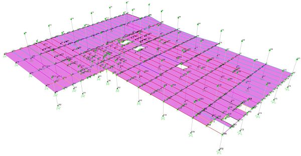
The figure below shows a finite element model created at ESI Engineering for a large hospital project. The methodology of Chapter 7 was applied.

A SAP2000 finite element model comprising a large area of a hospital floor with numerous operating rooms.
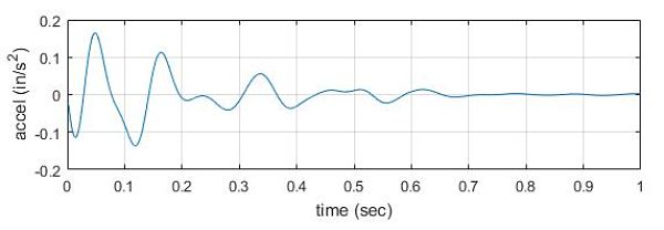
Once the FRF has been obtained, the resonant response calculations are fairly straightforward. However the impulse response is more complex. It requires computation of the effective impulse response for each mode of the structure up to a recommended frequency of 20 Hz, then a superposition of all these response time histories – each one is a damped sinusoid – to obtain the total impulse response. Since 50-100 modes or more may be required to reach 20 Hz, this represents some number crunching that can only be carried out by post-processing the FEA results. The figure below shows a typical impulse response time history obtained in this manner using SAP2000 and post-processing software developed at ESI Engineering. The actual footfall response would be represented by a train of these individual responses, one for each step and separated by the time between steps.

A sample acceleration time history computed using Chap. 7 of the new DG11.
The peak of this acceleration time history can be converted into other useful measures of vibration such as third octave spectral velocity and acceleration, and narrowband spectral velocity and acceleration. These conversions, which are supplied in Chapter 7, are extremely valuable.
Bottom Line
For engineer who has been using Design Guide 11 for many years, the new DG11 will require some getting used to when it comes to sensitive equipment. The computations are considerably more complex. The good news is that FEA and post processing of the output can provide relief from the tedious calculations. With many walker and receiver locations included in a single finite element model, this can be a real lifesaver.
ESI Engineering implemented the new DG11 Chapter 7 methodology recently on a large hospital project with many operating rooms. Our in-house post processing allowed us to look at many walker and receiver locations simultaneously. All walker and receiver locations are input as groups into the FEA software. For each receiver (OR), the software computes the FRFs for multiple walkers and determines which one creates the highest response. This FRF is then used to carry out the computations discussed above, with the walking speed specified by the user.
Non FEA-based software called FloorVibe, developed by Dr. Thomas Murray, has been available for the implementation of the previous edition of DG11. A new version of FloorVibe is reportedly under development.
The bottom line is that understanding the changes in Chapter 6 and Chapter 7 on sensitive equipment really requires working through detailed computations on your specific project. We hope that this brief summary gives some idea of what to expect. Inevitably, you will have questions on how to apply some of the concepts and equations. ESI is ready to help you sort things out and make your next project successful.

